Description
RS-FS-9001 Horner Electric
высотой 3U, расположенный в раме управления под DSPX.
волоконно – оптический разъем на передней панели и передаются в модуль обнаружения заземления.
ABB: Запасные части для промышленных роботов серии DSQC, Bailey INFI 90, IGCT, например: 5SHY6545L0001 AC1027001R0101 5SXE10 – 0181, 5SHY3545 L0009, 5SHI3545L0010 3BHB013088 R0001 3BHE009681R0101 GVC750BE101, PM866, PM861K01, PM864, PM510V16, PPD512, PPPD113, PP836A, P865A, 877, PPP881, PPPP885, PPSL500000 4 3BHL00390P0104 5SGY35L4510 и т.д.
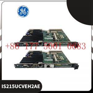
General Electric: запасные части, такие как модули, карты и приводы. Например: VMVME – 7807, VMVME – 7750, WES532 – 111, UR6UH, SR469 – P5 – HI – A20, IS230SRTDH2A, IS220PPDAH1B, IS215UCVEH2A, IC698CPE010, IS200SRTDH2ACB и т.д.
Система Bently Nevada: 350 / 3300 / 1900, предохранительные зонды и т.д., например: 3500 / 22M, 3500 / 32, 3500 / 15, 3500 / 23500 / 42M, 1900 / 27 и т.д.
Системы Invis Foxboro: Серия I / A, управление последовательностью FBM, трапециевидное логическое управление, обработка отзыва событий, DAC,
обработка входных / выходных сигналов, передача и обработка данных, такие как FCP270 и FCP280, P0904HA, E69F – TI2 – S, FBM230 / P0926GU, FEM100 / P0973CA и т.д.
Invis Triconex: Модуль питания, модуль CPU, модуль связи, модуль ввода – вывода, например 300830937214351B, 3805E, 831235114355X и т.д.
Вудворд: контроллер местоположения SPC, цифровой контроллер PEAK150, например 8521 – 0312 UG – 10D, 9907 – 149, 9907 – 162, 9907 – 164, 9907 – 167, TG – 13 (8516 – 038), 8440 – 1713 / D, 9907 – 018 2301A, 5466 – 258, 8200 – 226 и т.д.
Hima: модули безопасности, такие как F8650E, F8652X, F8627X, F8678X, F3236, F6217, F6214, Z7138, F8651X, F8650X и т.д.
Honeywell: Все платы DCS, модули, процессоры, такие как: CC – MCAR01, CC – PAIH01, CC – PAIH02, CC – PAIH51, CC – PAIX02, CC – PAON01, CC – PCF901, TC – CR014, TC – PD011, CC – PCNT02 и т.д.
Motorola: серии MVME162, MVME167, MVME172, MVME177, такие как MVME5100, MVME5500 – 0163, VME172PA – 652SE, VME162PA – 344SE – 2G и другие.
Xycom: I / O, платы VME и процессоры, такие как XVME – 530, XVME – 674, XVME – 957, XVME – 976 и т.д.
Коул Морган: Сервоприводы и двигатели, такие как S72402 – NANA, S6201 – 550, S20330 – SRS, CB06551 / PRD – B040SSIB – 63 и т. Д.
Bosch / Luxer / Indramat: модуль ввода / вывода, контроллер PLC, приводной модуль, MSK060C – 0600 – NN – S1 – UP1 – NNN, VT2000 – 52 / R900033828, MHD041B – 144 – PG1 – UN и т.д.
Implementation of communication between ABC industrial robot and PLC based on DeviceNet fieldbus technology
introduction
In modern production systems, industrial robots and PLCs need to communicate and collaborate to complete production tasks. That is, the
industrial robots output signals to the PLC, allowing the PLC to control related equipment to drive the robot”s front-end tools. This article
mainly analyzes the communication problems between ABB industrial robots and PLC based on DeviceNet fieldbus technology.
DeviceNet is a common network communication method in the field of automation. ABB industrial robots establish a network to communicate with
Siemens PLC based on the DeviceNet network.
1Configure DSQC652
There are mainly 5 types of standard I/0 boards commonly used in ABB industrial robots [2]. Except for the different addresses assigned to
them during setup, their configuration methods are basically the same. This article mainly analyzes the ABB standard I/0 board DS0C652, which
mainly builds communication modules based on the DeviceNet network. The DS0C652 board has a distributed I/O module with 16 digital input and 16
digital output interfaces. The board is installed in the ABB industrial robot control cabinet. First, define the specific operation steps of the DS0C652 board,
enter the teach pendant control panel, then enter the configuration menu (Figure 1), select the DeviceNetDevice menu, and add a template to enter Figure 2.
ABB standard I/0 board is hung on the DeviceNet
network, so the address of the module in the network must be set. The jumpers 6 to 12 of terminal x5 are used to determine the address of the module.
The available address range is 10 to 63. Modify the parameters in the template parameters to complete the DS0C652 board settings. Click the drop-down
menu to select the “Use value from template” row, select
“DS0C65224VDCI/0Device”, and then the parameters that need to be set include the address of the I/0 board in the bus.
Figure 1 Configuring DSQC652
2Configure signals and parameters
After completing the DS0C652 board setting, the I/0 signal setting will be performed. Setting the I/0 signal is the basis for establishing communication with
the PLC. The PLC communicates and transmits data with the ABB industrial robot through the I/0 signal and the DS0C652 board. As shown in Figure 3, in the
signal configuration interface, there are many default I/0 points after the system is established. Modification is not allowed. Click “Add” to add signals. When setting
input and output signals, their address range is 0~15. First, enter the signal menu in the configuration options to set the input and output types, and modify the corresponding parameters.
After completing the settings, the computer prompts that you need to restart the settings. If there are multiple signals that need to be defined and the waiting time
is long after restarting multiple times, you can click “Cancel” and wait for all signals to be defined before clicking the “Yes” button to restart. After the signal settings are
completed, click to select “Input and Output” in the ABB menu to check whether all signals have been set.
Figure 2 Configure DSQC652 parameters
Figure 3 Signal parameter settings
During the signal establishment process, attention should be paid to the DSoC652 port and PLC port addresses used, and the corresponding address table should be
established, as shown in Table 1. The robot interacts with the PLC through I/O signals. During the setting process, there must be no errors in the port and address number
of the PLC connected to the DSoC652. If the address is set incorrectly, the communication between the robot and the PLC will not work properly.
The entire robot teaching pendant setting process is shown in Figure 4.
1769-L32E Allen-Bradley Programmable automation controller
1769-L30ERMS Allen-Bradley CompactGuardLogix controller
1769-L24ER-QBFC1B CompactLogix 5370 L2 controller
1769-IT6 Thermocouple / milivolt Input Module
1769-IF8 Compact I/O analog input module
1769-IA16 Allen-Bradley 16 Channel Input Module
1769-ADN DeviceNet communication module
1762-L40BWAR Programmable Logic Controller (PLC)
1762-IF4 Differential channels analog input module
1757-SRM ControlLogix System Redundancy Module
1756-TBNH removable terminal block or RTB module
1756-RMB ControlLogix Redundancy module
1756-RM redundant module
1756-OF8 analog output module
1756-PA75RA ControlLogix Redundant Power Supply
1756-OF4 ControlLogix Four (4) channel analog output module
1756-OB32 ControlLogix Discrete output module
1756-L542 Allen-Bradley SLC 5/03 controller
1756-L75 Allen-Bradley ControlLogix Controller
1756-L71S Programmable controller
1756-L71 ControlLogix Logix5571 processor module
1756-L61 ControlLogix controller
1756-IF8H ControlLogix I/O module
1756-IB32 Input module
1756-IB16 I/O module
1756-ENBT Optical fiber interface board module
1756-EN2TXT Ethernet /IP module
1756-EN2TR Communication module
1756-EN2TEthernet /IP module
1756-DNB Scanner module
1756-DHRIO Programmable controlle
1756-BATM Programmable logic controller
1756-A13 chassis
1755T-PMPP-1700 Touch screen
1755-A6 module
1747-SDN Communication module
1747-KE Communication module
1747-FC Input/output module
1747-DCM Input/output module
1747-C10 driver
1747-ACNR15 Processor module
1746-P4 Power module
1746-OV8 Programmable controller
1746-OB16E Allen-Bradley Programmable controller
1746-OA8 Programmable controller
1746-IV32 Allen-Bradley SLC 500 Discrete Input module
1746-A2 Programmable logic control
мы организуем фото на складе, чтобы подтвердить
чтобы вернуть их вам. Конечно, мы ответим на ваши озабоченности как можно скорее.



Reviews
There are no reviews yet.