")
Description
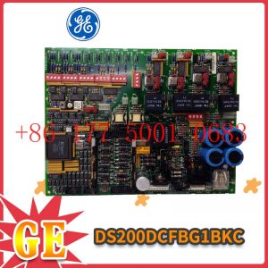
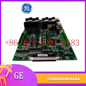
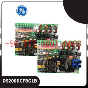
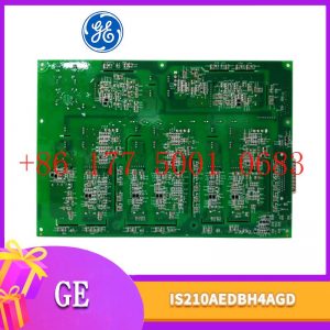
IS200BAIAHIB/RM Boards & Turbine Control Module
(2) Select S7-315-2DP as the main station system, import the GSD (device database) file of NPBA-12 into the STEP7 programming environment, and configure the software
to configure NPBA-12 with S7-315-2DP as the main station. DP online, and select the PPO type to use. This design uses PPO4 to set the site network address. In the Profibus
structure of the variable frequency drive device, ABB frequency converters use the Profibus-DP communication module (NPBA-12) for data transmission, which is
mainly periodic: the host reads the input information from the slave station and sends the output information back to the slave station. ,
so it is necessary to call two system function blocks SFC14 and SFC15 in the PLC main program to read and write these data to achieve communication control to
the frequency converter;
(3) Create a data block in the main PLC program for data communication with the frequency converter; establish a variable table for observing the real-time
communication effect.
4 Inverter operation settings
After the frequency converter and PLC are connected to a network using Profibus-DP fieldbus, in addition to programming in the PLC automation system,
appropriate parameter settings must also be performed on each frequency converter.
After the communication cable is connected, start the inverter and complete the setting of the inverter communication parameters.
4.1 Basic settings
(1) 51.01—Module type, this parameter displays the module model detected by the transmission device. Its parameter value cannot be adjusted by the
user. If this parameter is not defined, communication between the module and the drive cannot be established.
(2) 51.02—This parameter selects the communication protocol, “0” selects the Profibus-DP communication protocol.
(3) 51.03—This parameter is Profibu
The PPO type selected by s connection, “3” is PPO4, but the PPO type on the inverter should be consistent with the PPO type configured on the PLC.
(4) 51.04—This parameter is used to define the device address number, that is, the site address of the frequency converter. Each device on the Profibus
connection must have a separate address. In this design, the two frequency converters are stations 2 and 3 respectively. [1]
4.2 Connection of process parameters
The process parameter interconnection completes the definition and connection of the corresponding parameters of the NPBA-12 dual-port RAM
connector and the frequency converter, including the connection from the master station (PLC) to the frequency converter and the connection from the frequency
converter to the master station (PLC). Set the following connection parameters on the frequency converter.
(1) PZD value sent from PLC to transmission inverter
PZD1—control word, such as start enable, stop, emergency stop and other control commands of the frequency converter;
PZD2—frequency setting value of the inverter.
(2) PZD value sent from the transmission inverter to the PLC
PZD1—status word, such as alarm, fault and other inverter operating status;
PZD2—actual speed value, current actual value, etc. of the frequency converter.
5 Conclusion
After the inverter control system adopts the Profibus-DP fieldbus control mode, the entire system not only has strong reliability and is easy to operate, but also can
be flexibly modified according to process needs. After this system was applied in Jigang Baode Color Plate Co., Ltd., it has been running well and has provided a successful
example for the future automation equipment (network communication of different manufacturers) of the head office.
New technology from Swiss ABB Group: Complete car charging in 15 seconds
This technology can charge a car in 15 seconds
The Swiss ABB Group has developed a new electric bus technology that can complete vehicle charging in 15 seconds . No other company”s battery technology can achieve this performance.
ABB has developed a technology called “Flash Charging” that allows an electric bus with 135 passengers to charge at charging points along the route. The charging point has a
charging power of 400 kilowatts and is located above the vehicle. The charging point is connected to a moving arm controlled by a laser and can charge the car battery in 15 seconds. Its
minimal design will help protect the urban environment and surrounding landscape.
The idea behind this design is to give the electric bus enough power to travel to the next charging station after one charge. The end of the line will allow for long periods of full charging
, with the car able to travel longer distances on a full charge. In addition to faster charging times, the system uses a carbon-emission-free solution called
TOSA to obtain electricity from clean hydroelectric power stations.
ABB initially plans to use this technology between Geneva Airport and the Palexpo International Convention and Exhibition Center. If the test is successful
, it will be deployed to public transportation systems. This is more cost effective and environmentally friendly.
ABB Executive Chief Technology Officer Claes Rytoft said: “With flash charging, we can trial a new generation of electric buses for large-scale transportation
in cities. This project will provide greater flexibility, cost-effectiveness and flexibility.” Paving the way for a lower public transport system while reducing pollution and noise.”


Reviews
There are no reviews yet.