")
Description
hardware flow control. It is an ideal choice in the field of industrial automation.
user experience
Secondly, if power system engineers are to consider the convenience and speed of using the product in the future, operability needs to be improved while ensuring stability.
This requires a simple self-service system and an operation interface with good visual effects that can meet the needs of users. Some operating habits and other aspects
* cut costs
Furthermore, since there are many nodes in the power system, the same product needs to be deployed on many nodes. Then when the quantity of required products increases,
cost issues will inevitably be involved. How to solve the research and development, construction and installation of products and better reduce operating expenses is also a major issue that ABB needs to consider.
Implementation of communication between Omron vision system and ABB industrial robot
introduction
In modern production processes, vision systems are often used to measure and identify products, and then the results are transmitted to industrial robots for work
through communications . In this process, communication settings are very important. This article analyzes the communication implementation process between the Omron
FH-L550 vision system and ABB industrial robots. The main task is to enable the vision system to provide data detection results for ABB industrial robots, and the industrial robots
perform related operations based on the data results. This article mainly discusses the entire process of visual system communication transmission implementation.
1Ethernet-based communication settings in vision software
The main communication methods of Omron FH-L550 vision system controller are as follows [2], namely: parallel communication, PLCLINK communication, Ethernet
communication, EtherCAT communication, and protocol-free communication. These five communication methods have their own characteristics in the communication process.
In modern equipment, Ethernet communication
(Ethernet communication) is the most common, so this article uses the Ethernet communication method as an example to analyze and explain.
First, select the “Tools” option in the main interface, select the “System Settings” menu (Figure 1), after entering the “System Settings” menu, click the “Startup Settings” option,
and select the “Communication Module” tab (Figure 2 ), after completing the above settings, return to the main interface to save the settings (Figure 3). Finally, select the function
menu to perform system restart settings, and wait for the system to complete the restart before proceeding to the next step.
After the system restarts, click the “System Settings” menu again and select the “Ethernet (No Protocol (UDP))” option (Figure 4). In this option, there will be parameter settings
such as IP address and port. What needs to be noted here are the two IP address parameters. The parameters in “Address Setting 2” need to be filled in. The information that needs
to be filled in includes the IP address of the vision controller, subnet mask, default gateway and DNS server.
In the port number setting of “Input/Output Settings” at the bottom of the menu, set the port number for data input with the sensor controller. Note that the port number should
be the same as the host side, and finally complete the settings and corresponding data saving work.
2ABB industrial robot communication settings
First, configure the WAN port IP address for the ABB industrial robot. Select the control panel in the teach pendant, then select configuration, then select communication in
the theme, click IPSetting, set the IP information and click “Change” to save the IP information.
Next, use the SocketCreate robot command to create a new socket using the streaming protocol TCP/IP and assign it to the corresponding variable (Figure 5). Then
use the SocketConnect command to connect the socket to the remote computer. After the communication connection is completed, it is necessary to send and receive
information from the visual system. To send information, use the SocketSend instruction to send data instructions to the remote computer. After the vision system collects
information and makes judgments, the industrial robot system will receive data from the remote computer. The data reception is completed using the
SocketReceive instruction. This instruction stores the data in the corresponding string variable while receiving the data. Useful information needs to be extracted from the
received data information, which requires StrPart to find the specified character position instruction, extract the data at the specified position from the string, and assign the
result to a new string variable. Finally, when the socket connection is not in use, use SocketCloSe to close it.
https://www.xmamazon.com
https://www.xmamazon.com
https://www.plcdcs.com/
www.module-plc.com/
https://www.ymgk.com
LAIB V3.0_A00 034STN1-00-300-RS
ATKB_V5.0_A01 03ZSTI4-01-501
ATKB_V5.0_A01 03ZSTI4-00-501
FPB_V3.0_A01 03ZSTJ1-00-301-RS
DSPB_V4.0_A02 03ZSTI7-00-402-RS
PUIM V2.0 034STM4-00-200-RS
DUDT_DETECTION_V2.0_A01 03ZSTJ0-00-201-RS
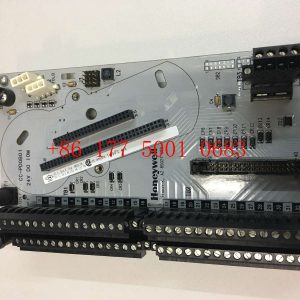
IPB PCB V2.0_A01 03ZSTL6-00-201-RS printed circuit board
IPB PCB V2.0_A01 03ZSTL6-00-201-RS printed circuit board
149992-01 BENTLY 3500/33 calories Relay Output Module
IS220PVIBH1A 336A4940CSP16 GE Vibration Monitor Pack
RH916XZ foxboro FBM247 Fieldbus module
IS420UCSCH2A-C-V0.1-A Four core controller GE
5SHY3545L0010 3BHB013088R0001 3BHE009681R0101 GVC750BE101
FROSOFT MVI56E-MNETXT Enhanced communication module
REXROTH HDS02.2-W040N-HS12-01-FW Servo controller
DEUBLIN 904-120-188
810-234640-312 LAM Printed circuit board
SAIA 52030C10 PCD2.W200 Analog input module
VM600 XIO16T 620-002-000-113 620-003-111-112 VM600 XIO16T
200-595-031-111 VM600 CPUM modular CPU card
VM600 MPC4 200-510-071-113 200-510-111-034 machinery protection module
VM600 XMV16 600-003 620-001-001-116 condition monitoring module for vibration
VM600 IOC4T 200-560-000-018 200-560-101-015 voltage-drop adaptor
VM600 XIO16T 620-002-000-113 620-003-111-112 extended condition monitoring modules
NI-9853 C series CAN interface module
DS200SLCCG1ACC LAN communication card
DS200UDSAG1ADE exciter board
330180-51-CN 3300 XL preprocessor sensor
Approach probe on 330103-00-03-10-02-CN
330130-040-00-05 3300 XL Extension cable
330103-00-03-10-02-CN Approach probe
330103-00-03-10-02-00 short range detector
330104-06-13-10-01-CN 3300 XL 8mm short-range probe
CDAQ-9185 785064-01 NI CompactDAQ chassis
NI-9205 779357-01 C Series voltage input module
NI-9361 783407-01 C Series counter input module
CM597-ETH 1SAP173700R0001 Communication module
330104-11-22-10-01-CN 3300 XL 8mm short-range probe
FBM218 RH922VW HART Redundant communication output interface module
PXI-6602 counter/timer equipment
330703-00-060-10-02-00 3300 XL 11mm short range probe
330703-000-070-10-01-EN 3300 XL 11mm short-range probe
PXIE-1065 PXI chassis NI
330130-080-01-00 3300 XL standard extension cable
330180-X1-00 3300 XL preprocessor sensor
330104-07-22-10-02-00 3300 XL 8mm short range probe
2711P-T9W21D8S PanelView Plus 7 Graphics terminal
MDD112C-N-030-N2L-130GA0 servo motor
C400/A8/1/1/1/00 ELAU controller
MDD112D-N-020-N2L-130GA0 servo motor


Reviews
There are no reviews yet.