Sale!

DS200DSPCH1ADA Exciter terminal board

Original price was: $1,888.00.Current price is: $1,688.00.

МодельDS200DSPCH1ADA

Первоначальная гарантия на один год.
DS200DSPCH1ADA Параметры

DS200DSPCH1ADA Размер 30 * 20 * 30
DS200DSPCH1ADA Вес 2 кг

Контактное лицо: г – н Рай

WeChat: 17750010683

WhatsApp: + 86 177500 10683

Электронная почта 3221366881@qq.com

Category:

Description

DS200DSPCH1ADA Exciter terminal board
DS200DSPCH1ADA Exciter terminal board Product details:

DS200DSPCH1ADA Technical Manual

DS200DSPCH1ADA Weight:1.8KG
DS200DSPCH1ADA Size: 20* 20 * 10cm
DS200DSPCH1ADA instructions
DS200DSPCH1ADA PDF
DS200DSPCH1ADA  – это панель связи возбудителя для передачи данных между контроллерами.
666666 Описание функций
ISBus – это защищенный интерфейс связи GE, используемый для передачи данных между контроллерами M1, M2 и C возбудителя. EISB – это модуль с одним слотом и высотой 3U, расположенный в раме управления под DSPX.
DS200DSPCH1ADA  Сигналы тока и напряжения от магнитного поля генератора (включая, при необходимости, возбудитель) принимаются через волоконно – оптический разъем на передней панели и передаются в модуль обнаружения заземления.
Применение данных
У EISB нет светодиодных индикаторов, трамплинов или предохранителей.
Соединитель
Следующие волоконно – оптические разъемы расположены на передней панели платы и используются для приема и передачи сигналов преобразования частоты DS200DSPCH1ADA :
• Ввод напряжения постоянного тока на месте для генераторов с пластиной EDCF
• Ввод тока на панели EDCF в аэропорту постоянного тока
Ввод напряжения возбудителя EDCF (необязательно)
Ввод тока в возбудитель EDCF (необязательно)
• Ввод напряжения в детектор заземления
• Переключатель сброса напряжения на выходе из приемника заземления также вогнут за отверстие в нижней части передней панели
Contact person: Mr. Lai
Mobil:17750010683
WeChat:17750010683
WhatsApp:+86 17750010683

In the formula, a is the design acceleration/deceleration value: s is the current actual position value of the
elevator: V2 is the maximum speed of the elevator at this position.

Considering that the lifting system needs to enter the parking track at a low crawling speed when entering the
end of the stroke to avoid equipment damage caused by large mechanical impact, therefore, when there are still
1~5m away from the parking position, the lifting speed is limited to 0.5m/ below s.

Since the instantaneous speed before parking is very low, the position accuracy of the system”s parking can
be relatively improved, which is particularly important when the auxiliary shaft is lifted.

2.2 Design and implementation of security protection functions

Mines have particularly strict requirements on safety and reliability of hoist control systems [5]. While ensuring high
reliability of electrical control equipment, the control system also sets up multiple protections in key links where failures
may occur, and detects the actions and feedback signals of these protection devices in real time.

First of all, monitoring the operating status of the elevator is the top priority in the safety protection
function of the elevator control system. In the control system, the operating speed and position of the
motor are monitored at all times, and the current position and speed values ​​are compared with the system”s
designed speed and position curve. Once it is found that the
actual operating speed of the hoist exceeds the designed speed value, immediately Issue an emergency
stop command and strictly ensure that the lifting speed is within the safe monitoring range during the entire
lifting process. At the same time, position detection switches are
arranged at several locations in the wellbore, and these position detection switches correspond to specific
position values ​​and corresponding speed values. When the elevator passes these switches, if it is found through
encoder detection that the actual speed value and position deviate from the values ​​corresponding to the position
detection switch, the control system will also judge that it is in a fault state
and immediately implement an emergency stop.

In order to determine whether the encoder connected to the main shaft of the elevator drum is normal,
two other encoders are installed on the elevator. In this way, the position and speed detection values
​​of the three encoders are always compared. Once it is found that the deviation between the detection
value of one encoder and the detection value of the other two encoders exceeds the allowable range,
the control system will immediately consider it to have entered a fault state and implement an emergency stop. Protective action.

3 Conclusion

The efficient and safe operation of main well equipment is an important guarantee for its function.
In the application of mine hoist, the 800xA system designed speed curve, self-correction, various
self-diagnosis and protection functions according to the specific process characteristics of the main
shaft mine hoist, which has achieved good results in practical applications.
489-P1-HI-A20-E GE Relay
489-P5-HI-A20-E  GE  Enhanced display
IS420ESWAH3A GE Ethernet switch
IS420ESWAH2A GE Ethernet switch
IS420ESWAH1A GE Control system
IS420YDOAS1B GE relay
IS420YAICS1B GE Analog input
IS420UCSDH1A GE processor
IS420UCSCH1C GE One of the UCSC controllers
IS420UCSCH1B GE  UCSC controller
IS420UCSBS1A GE Control safety system
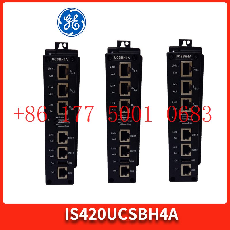
IS420UCSBH4A GE High speed application
IS420UCSBH3A GE UCSB controller
IS420UCSBH1A GE controller
IS420UCPAH2A GE controller
IS420UCPAH1A GE processor
IS420PUAAH1A GE Universal input
IS420PSCAH1B GE  Communication module
IS420PPNGH1A GE Gateway module equipment
IS420PFFAH1A GE Bus gateway
IS420ESWBH5A GE Single mode fiber interface
IS420ESWBH4A GE ESWB IONet switch
IS420ESWBH1A GE IONet switch
IS420ESWAH5A GE  ESWA switches
IS420ESWAH4A GE  switch
469-P5-LO-A20-T GE Ethernet connection
469-P5-LO-A20-E  GE
469-P5-LO-A20 GE Low control power
469-P5-HI-A20-T-H GE Ethernet port
469-P5-HI-A20-T GE Ethernet communication
469-P5-HI-A20-E-H GE Output relay
469-P5-HI-A20 GE Motor management relay
469-P5-HI-A1-E GE  relay
469-P1-HI-A20-E-H GE
469-P1-HI-A1-E-H GE relay
469-P1-HI-A1-E GE Display screen
489-P5-LO-A20 GE Multiplex relay
SR469-P5-HI-A20-H GE  relay
SR469-P5-HI-A20-E GE Control power supply
SR469-P5-HI-A20 GE Analog output
469-P5-HI-A20-E  GE Control power supply
469-P1-HI-A20-E-H GE Analog output
369-LO-R-M-0-D-0-E GE Output relay
369-L0-R-M-0-D-0-E GE Enhanced motor
369-HI-R-M-F-0-H-E GE Relay
369-HI-R-M-F-0-H-E GE Motor protective relay
369-HI-R-M-0-0-H-0 GE Motor management relay
369-HI-R-M-0-0-0 GE Alternating current motor
369-HI-R-M-0-0 GE Resistance temperature detector
369-HI-R-B-0-E-0-E GE optically isolated
369-HI-R-B-0-0 GE Motor management
369-HI-R-0-F-0-0-E GE relay
369-HI-R-0-0-0-0-E GE relay

Reviews

There are no reviews yet.

Be the first to review “DS200DSPCH1ADA Exciter terminal board”

Your email address will not be published. Required fields are marked *