Sale!

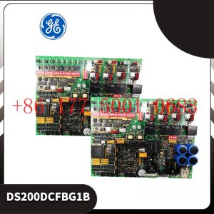
DS200ACNAG1ADD Boards & Turbine Control Module

Original price was: $1,888.00.Current price is: $1,688.00.

МодельDS200ACNAG1ADD

Первоначальная гарантия на один год.
DS200ACNAG1ADD Параметры

DS200ACNAG1ADD Размер 30 * 20 * 30
DS200ACNAG1ADD Вес 2 кг

Контактное лицо: г – н Рай

WeChat: 17750010683

WhatsApp: + 86 177500 10683

Электронная почта 3221366881@qq.com

Category:
Phone: +86 17750010683
Email: 3221366881@qq.com
connect:Mr. Lai

Description

DS200ACNAG1ADD Boards & Turbine Control Module
DS200ACNAG1ADD Boards & Turbine Control Module Product details:

DS200ACNAG1ADD Technical Manual

DS200ACNAG1ADD Weight:1.8KG
DS200ACNAG1ADD Size: 20* 20 * 10cm
DS200ACNAG1ADD instructions
DS200ACNAG1ADD PDF
DS200ACNAG1ADD  – это панель связи возбудителя для передачи данных между контроллерами.
666666 Описание функций
ISBus – это защищенный интерфейс связи GE, используемый для передачи данных между контроллерами M1, M2 и C возбудителя. EISB – это модуль с одним слотом и высотой 3U, расположенный в раме управления под DSPX.
DS200ACNAG1ADD  Сигналы тока и напряжения от магнитного поля генератора (включая, при необходимости, возбудитель) принимаются через волоконно – оптический разъем на передней панели и передаются в модуль обнаружения заземления.
Применение данных
У EISB нет светодиодных индикаторов, трамплинов или предохранителей.
Соединитель
Следующие волоконно – оптические разъемы расположены на передней панели платы и используются для приема и передачи сигналов преобразования частоты DS200ACNAG1ADD :
• Ввод напряжения постоянного тока на месте для генераторов с пластиной EDCF
• Ввод тока на панели EDCF в аэропорту постоянного тока
Ввод напряжения возбудителя EDCF (необязательно)
Ввод тока в возбудитель EDCF (необязательно)
• Ввод напряжения в детектор заземления
• Переключатель сброса напряжения на выходе из приемника заземления также вогнут за отверстие в нижней части передней панели
Contact person: Mr. Lai
Mobil:17750010683
WeChat:17750010683
WhatsApp:+86 17750010683

Implementation of communication between ABC industrial robot and PLC based on DeviceNet fieldbus technology
introduction

In modern production systems, industrial robots and PLCs need to communicate and collaborate to complete production tasks. That is, the
industrial robots output signals to the PLC, allowing the PLC to control related equipment to drive the robot”s front-end tools. This article
mainly analyzes the communication problems between ABB industrial robots and PLC based on DeviceNet fieldbus technology.
DeviceNet is a common network communication method in the field of automation. ABB industrial robots establish a network to communicate with
Siemens PLC based on the DeviceNet network.

1Configure DSQC652

There are mainly 5 types of standard I/0 boards commonly used in ABB industrial robots [2]. Except for the different addresses assigned to
them during setup, their configuration methods are basically the same. This article mainly analyzes the ABB standard I/0 board DS0C652, which
mainly builds communication modules based on the DeviceNet network. The DS0C652 board has a distributed I/O module with 16 digital input and 16
digital output interfaces. The board is installed in the ABB industrial robot control cabinet. First, define the specific operation steps of the DS0C652 board,
enter the teach pendant control panel, then enter the configuration menu (Figure 1), select the DeviceNetDevice menu, and add a template to enter Figure 2.
ABB standard I/0 board is hung on the DeviceNet
network, so the address of the module in the network must be set. The jumpers 6 to 12 of terminal x5 are used to determine the address of the module.
The available address range is 10 to 63. Modify the parameters in the template parameters to complete the DS0C652 board settings. Click the drop-down
menu to select the “Use value from template” row, select
“DS0C65224VDCI/0Device”, and then the parameters that need to be set include the address of the I/0 board in the bus.
Figure 1 Configuring DSQC652

2Configure signals and parameters

After completing the DS0C652 board setting, the I/0 signal setting will be performed. Setting the I/0 signal is the basis for establishing communication with
the PLC. The PLC communicates and transmits data with the ABB industrial robot through the I/0 signal and the DS0C652 board. As shown in Figure 3, in the
signal configuration interface, there are many default I/0 points after the system is established. Modification is not allowed. Click “Add” to add signals. When setting
input and output signals, their address range is 0~15. First, enter the signal menu in the configuration options to set the input and output types, and modify the corresponding parameters.
After completing the settings, the computer prompts that you need to restart the settings. If there are multiple signals that need to be defined and the waiting time
is long after restarting multiple times, you can click “Cancel” and wait for all signals to be defined before clicking the “Yes” button to restart. After the signal settings are
completed, click to select “Input and Output” in the ABB menu to check whether all signals have been set.
Figure 2 Configure DSQC652 parameters
Figure 3 Signal parameter settings

During the signal establishment process, attention should be paid to the DSoC652 port and PLC port addresses used, and the corresponding address table should be
established, as shown in Table 1. The robot interacts with the PLC through I/O signals. During the setting process, there must be no errors in the port and address number
of the PLC connected to the DSoC652. If the address is set incorrectly, the communication between the robot and the PLC will not work properly.

The entire robot teaching pendant setting process is shown in Figure 4.
Excitation system ABB module TB825
Excitation system ABB module TB820V2
Excitation system ABB module TB820
Excitation system ABB module TB815
Excitation system ABB module TB811
Excitation system ABB module TB810
Excitation system ABB module TB807
Excitation system ABB module TB806
Excitation system ABB module TB805
Excitation system ABB module TB711F
Excitation system ABB module TB521-ETH
Excitation system ABB module TAS01
Excitation system ABB module TAS.580.0600G00 V01
Excitation system ABB module TAS.580.0560G00
Excitation system ABB module TAS.580.0540G00
Excitation system ABB module TA924F
Excitation system ABB module TA724F
Excitation system ABB module TA526
Excitation system ABB module TA525
Excitation system ABB module TA524
Excitation system ABB module TA523
Excitation system ABB module SYNPOLD CMA132
Excitation system ABB module SYNCHROTACT5 3BHB006713R0217
Excitation system ABB module SYN5202A
Excitation system ABB module SYN5202
Excitation system ABB module SYN5201a-Z,V217 3BHB006714R0217
Excitation system ABB module SY809F
Excitation system ABB module SV541
Excitation system ABB module STT02E
Excitation system ABB module STC2BE
Excitation system ABB module STC2AE
Excitation system ABB module STBNIP2311
Excitation system ABB module SS832 3BSC610068R1
Excitation system ABB module SS832
Excitation system ABB module SS822Z
Excitation system ABB module SS822
Excitation system ABB module SR511 3BSE000863R1
Excitation system ABB module SR511 3BSE000863R0001
Excitation system ABB module SPTPS13
Excitation system ABB module SPTKM01
Excitation system ABB module SPSET01
Excitation system ABB module SPSED01
Excitation system ABB module SPNPM22
Excitation system ABB module SPNIS21
Excitation system ABB module SPMC2402
Excitation system ABB module SPMC1402
Excitation system ABB module SPIPT800
Excitation system ABB module SPIET800
Excitation system ABB module SPICT13A
Excitation system ABB module SPHSS13
Excitation system ABB module SPHSS03 Belica piece
Excitation system ABB module SPHSS03
Excitation system ABB module SPFEC12
Excitation system ABB module SPFCS01
Excitation system ABB module SPER1C1
Excitation system ABB module SPDSO14

Reviews

There are no reviews yet.

Be the first to review “DS200ACNAG1ADD Boards & Turbine Control Module”

Your email address will not be published. Required fields are marked *