Description
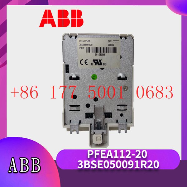
1MRK002133-ABR03 Контроллер ABB
CC – Link и другие. Каждый слот IO может быть выбран автономно в соответствии с потребностями клиента, а один модуль поддерживает до 16 каналов.
Технологии основаны на инновациях1MRK002133-ABR03 Предоставление клиентам высококачественных и надежных продуктов всегда было постоянным стремлением к нулю.
Давайте посмотрим на его инновации и различия с предшественниками: с жидкокристаллическим дисплеем, вы можете увидеть параметры связи, состояние канала IO,
информацию о версии модуля и так далее; 1MRK002133-ABR03 Отладка и обслуживание более интуитивно понятны; ABS огнестойкая пластиковая оболочка, небольшой размер,
легкий вес, с использованием совершенно новой пряжки монтажной карты, установка более прочная и надежная.
Implementation of communication between ABC industrial robot and PLC based on DeviceNet fieldbus technology
introduction
In modern production systems, industrial robots and PLCs need to communicate and collaborate to complete production tasks. That is, the
industrial robots output signals to the PLC, allowing the PLC to control related equipment to drive the robot”s front-end tools. This article
mainly analyzes the communication problems between ABB industrial robots and PLC based on DeviceNet fieldbus technology.
DeviceNet is a common network communication method in the field of automation. ABB industrial robots establish a network to communicate with
Siemens PLC based on the DeviceNet network.
1Configure DSQC652
There are mainly 5 types of standard I/0 boards commonly used in ABB industrial robots [2]. Except for the different addresses assigned to
them during setup, their configuration methods are basically the same. This article mainly analyzes the ABB standard I/0 board DS0C652, which
mainly builds communication modules based on the DeviceNet network. The DS0C652 board has a distributed I/O module with 16 digital input and 16
digital output interfaces. The board is installed in the ABB industrial robot control cabinet. First, define the specific operation steps of the DS0C652 board,
enter the teach pendant control panel, then enter the configuration menu (Figure 1), select the DeviceNetDevice menu, and add a template to enter Figure 2.
ABB standard I/0 board is hung on the DeviceNet
network, so the address of the module in the network must be set. The jumpers 6 to 12 of terminal x5 are used to determine the address of the module.
The available address range is 10 to 63. Modify the parameters in the template parameters to complete the DS0C652 board settings. Click the drop-down
menu to select the “Use value from template” row, select
“DS0C65224VDCI/0Device”, and then the parameters that need to be set include the address of the I/0 board in the bus.
Figure 1 Configuring DSQC652
2Configure signals and parameters
After completing the DS0C652 board setting, the I/0 signal setting will be performed. Setting the I/0 signal is the basis for establishing communication with
the PLC. The PLC communicates and transmits data with the ABB industrial robot through the I/0 signal and the DS0C652 board. As shown in Figure 3, in the
signal configuration interface, there are many default I/0 points after the system is established. Modification is not allowed. Click “Add” to add signals. When setting
input and output signals, their address range is 0~15. First, enter the signal menu in the configuration options to set the input and output types, and modify the corresponding parameters.
After completing the settings, the computer prompts that you need to restart the settings. If there are multiple signals that need to be defined and the waiting time
is long after restarting multiple times, you can click “Cancel” and wait for all signals to be defined before clicking the “Yes” button to restart. After the signal settings are
completed, click to select “Input and Output” in the ABB menu to check whether all signals have been set.
Figure 2 Configure DSQC652 parameters
Figure 3 Signal parameter settings
During the signal establishment process, attention should be paid to the DSoC652 port and PLC port addresses used, and the corresponding address table should be
established, as shown in Table 1. The robot interacts with the PLC through I/O signals. During the setting process, there must be no errors in the port and address number
of the PLC connected to the DSoC652. If the address is set incorrectly, the communication between the robot and the PLC will not work properly.
The entire robot teaching pendant setting process is shown in Figure 4.
SST-IBS-CLX-RLL
SST-ESR2-CLXT-RLL ETH/SER in Chassis Communication Module
SST-ESR2-CLX-RLL-C SST ETH/SER In Chassis Module
SST-ESR2-CLX-RLL Ethernet and serial communication modules
SST-ASI-SLC interface module
SST-ASI-CLX-S Interface communication module
SST-ASI-CLX communication module
PS56-LON-001 LonWorks Communication Interface Module
PC56-XP-IDE Modbus communication module
PS56-BAS-019 System communication module
MVI56-MNETC Communication module of TCP/IP protocol
MVI56-MNET ControlLogix Communication Module
MVI56-MBP Modbus Plus Dual Port Network Interface Module
MVI56-LTQ Valve Network Interface Module
MVI56-HART Multipoint Network Interface Module
MVI56-GSC interface module
MVI56-GEC Ethernet communication interface module
MVI56-EGD Ethernet network interface module
MVI56-DNPSNET Ethernet interface module
MVI56-DNP DNP 3.0 Master/Slave Network Interface Module
MVI56-DFCMR Master/Slave Network Interface Module
MVI56-DFCM communication module
MVI56-BSAPS Serial Slave Module
MVI56-ADM Programmable Application Development Module
MVI56-BAS communication module
MVI56-104S Ethernet Server Network Interface Module
MVI56-103M Master communication module
MVI56-101S Slave Network Interface Module
MVI56-101M Master Network Interface Module
MVI56E-MCM/MCMXT Master/Slave Enhanced Network Interface Module
MVI56E-FLN FA Control Network Enhanced Communication Module
MVI56E-DNPNET DNP3 Ethernet Module
MVI56E-SIE Industrial Ethernet communication module
MVI56E-LDM Linux development modules
MVI56E-61850S Server Communication Module
CLX-APACS Modules in the chassis
MVI56E-SMGC TPU general communication module
MVI56E-MNETXT Conformally coated communication modules
MVI56E-61850C Client Communication Module
VI56E-MNET Enhanced Network Interface Module
MVI56E-MCMR Enhanced Modbus Master/Slave Communication Module
MVI56E-GSC/GSCXT Serial Enhanced Communication Module
MVI56E-MNETR Enhanced Network Interface Module
MVI56E-MNETC/MNETCXT Enhanced Network Interface Module
MVI56E-MNETCR network interface module
MVI56-DNP Master/Slave Network Interface Module
MVI56-S3964R network interface module
MVI56-BAS Basic communication module
MVI56-104S Ethernet Server Network Interface Module
MVI56-EGD network interface module
MVI56E-AFC Enhanced Liquid and Gas Flow Computers
MVI56-LTQ Valve Network Interface Module
MVI56E-GEC Ethernet enhanced communication module
ILX56-PBM PROFIBUS DPV1 Master/Slave for ControlLogix®
ILX56-PBS PROFIBUS DPV1 Multi-Slave Module
81003-269-51-R Rectifier unit board A-B
MVI69E-GSC Enhanced Communication Module
5SHY3545L0014 3BHB013085R0001 IGCT MODULE


Reviews
There are no reviews yet.