Description
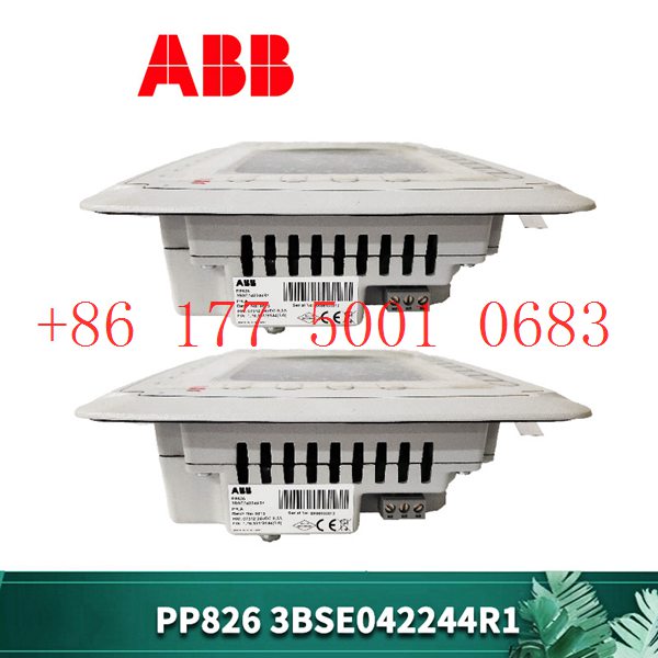
142DMB301CAAAA Электрический фильтр ABB
CC – Link и другие. Каждый слот IO может быть выбран автономно в соответствии с потребностями клиента, а один модуль поддерживает до 16 каналов.
Технологии основаны на инновациях142DMB301CAAAA Предоставление клиентам высококачественных и надежных продуктов всегда было постоянным стремлением к нулю.
Давайте посмотрим на его инновации и различия с предшественниками: с жидкокристаллическим дисплеем, вы можете увидеть параметры связи, состояние канала IO,
информацию о версии модуля и так далее; 142DMB301CAAAA Отладка и обслуживание более интуитивно понятны; ABS огнестойкая пластиковая оболочка, небольшой размер,
легкий вес, с использованием совершенно новой пряжки монтажной карты, установка более прочная и надежная.
Figure 4 Tool Framework
2.3Smart component creation
Call the Rotator component: This component is used to allow the rotatable grinding rotor to rotate during simulation to simulate the real grinding scene. In the
parameters of the Rotator component, set the reference to object, the reference object to the frame l, and the object to a copy of the rotor. (2) The rotary grinding rotor
can be rotated, and the speed is l20mm/s (the speed of the grinding head will affect the quality of the finished product) ), the reference center axis is: axis (based on frame
l, centerpoint x, y,: set to 0, 0, 0, Axis set x, y,: 0, 0, l000mm).
Call the Attach component: This component is used to allow the rotatable grinding rotor to be integrated with the tool body. When the tool body is installed
on the flange, it can follow the movement of the flange. In the parameters of the Attach component, set the sub-object to be a copy of the rotor (2) for the rotatable
polishing rotor, and the parent object is the tool body of a copy of the rotor. The offset and orientation are
based on the offset of point B relative to the origin. For setting, you can use the measurement tool in Robotstudio software to measure, and then set the parameters
after measurement.
Verification: Install a copy of the rotor tool body onto the robot flange, and then click Execute in the Attach component. You can observe whether the position of the
rotatable grinding rotor is correct at this time. If there is a deviation, adjust the position in time, as shown in the figure. 5 shown.
Figure 5 Tool installation
2.4 Create tool coordinate system
Use the six-point method to create the tool coordinate system Too1data on the robot teach pendant at the center of the rotor. Change the tool coordinate
system to Too1data in the basic options. At this time, click on the robot manual linear and you can drag the robot to move linearly at will.
2.5 Creating trajectories and programming
Determine the trajectory: According to the requirements of the work task, design the grinding trajectory around the workpiece and determine the trajectory
points and transition points required for the grinding trajectory. The grinding action process is shown in Figure 6.
Setting I/O and programming: Yalong IY-l3-LA industrial robot deburring and grinding system control and application equipment adopts 0sDC-52 6/o
communication board, the address is 10, Do1 is the digital output signal, the address is 1 . First set the I/O board, then set the I/O digital output signal Di1,
and then program on the simulation teaching pendant. The procedure is as follows:
PRoCmain()
setDo1: Set the Do1 signal to allow the external grinding rotor to start rotating.
waitTime1: The robot stays in place and does not move, waits for 1s, and lets the polishing rotor turn to the specified speed, transition
MoveAbsjjpos10NoEoffs,v1000,z50,Too1data1: The robot moves to the initial point jpos10 above point p10. Point jpos10 is used as the starting
point and end point of the robot”s action.
Move4p10,v1000,z50,Too1data1: Move straight line grinding to point p10
Move4pL0,v1000,z50,Too1data1: Move straight line grinding to pL0 point
Move4p30,v1000,z50,Too1data1: Move straight line grinding to point p30
Move4p40,v1000,z50,Too1data1: Move straight line grinding to p40 point
Move4p10,v1000,z50,Too1data1: Move straight line grinding to point p10
MoveAbsjjpos10NoEoffs,v1000,z50,Too1data1: The robot moves to the initial point jpos10 above point p10
waitTime1: wait 1s, transition
ResetDo1: Reset the Do1 signal to stop the rotor ENDPRoC
2.6 Simulation design and verification
Simulation design: Create a smart component to input the Di1 signal, and use the Di1 signal to simulate the external polishing start signal to
execute the Rotator component and Attach component of the smart component to achieve the visual effect of rotating and polishing the polishing rotor.
In the workstation logic design, the smart component input Di1 signal is associated with the robot Do1 signal, so that the robot signal Do1 can control
the smart component input Di1 signal, thereby controlling the start and stop of the rotation of the polishing rotor.
Verification: In the program of the teaching pendant, first set the pp command to move to Main, and then set the robot startup mode to automatic.
Click play in the simulation of Robotstudio software to verify whether the trajectory is consistent with the assumption, and optimize the path in time for
problems existing in the simulation.
3Summary and outlook
This design is based on the programming simulation of the Yalong Y4-1360A industrial robot deburring system to control the grinding robot workstation.
It covers aspects such as creating a workstation, setting
up tools, creating smart components, creating tool coordinate systems, creating trajectories, programming, simulation design, and verification. Starting
with it, the polishing simulation of the workstation is realized through the smart component function of Robotstudio software. The animation effect is intuitive
and lifelike, which not only facilitates teaching demonstrations, but also facilitates program debugging, and has application value for both production and teaching.
In the planning and design of the workpiece grinding trajectory, according to the different roughness and grinding amount process requirements of the
workpiece, the rotation speed, feed speed, feed amount, and grinding angle of the grinding rotor are also different. The feed amount can be adjusted in
time according to the on-site conditions. , feed speed, rotor speed, grinding angle and other parameters. After appropriate adjustments, the motion trajectory is written with the
corresponding program on the Robotstudio software to further reduce the possibility of robot collisions and singular points contained in the trajectory
during the actual debugging process. ,Optimize paths and improve debugging efficiency.
OS9-GNI-C20L | Alcatel-Lucent | Network interface module
NAIO-03F | ABB | Simulate I/O scaling
MVI56-BAS | prosoft | Communication module
INNPM12 | ABB | Network Processor Module
INNIS21 | ABB | Secondary module of the network interface
IMMFP12 | ABB | Processor Module
IEPAS01 | ABB | AC System Power Supply
EHDB520 | ABB | Electromagnetic contactor
EHDB280 | ABB | Electromagnetic contactor
EH370-30-22 | ABB | Electromagnetic contactor
DSQC664 | ABB | DSQC 664 3HAC030923-001 Driving system
DSQC661 | ABB | DSQC 661 3HAC026253-001 Power module
DSQC651 | ABB| DSQC 651 I/O module
DSQC 604 | ABB | DSQC604 Power supply
3HAB8101-19 DSQC545A | ABB| DSQC 545A Module drives the system
DSQC 539 | ABB | DSQC539 Robot parts
DSMB-01C | ABB| Power supply panel
DSDX452 | ABB| Input/output module
DS3820PS3A | GE| Gas turbine clamp
DS3810MM | GE | card
DPW03 | ABB| DPW 03 Power module
DAI04 | ABB | DAI 04 Analog Input Module
CP450 T | ABB| Control Panel
3BSE020520R1| ABB | Communication Unit
BRC300 | ABB | P-HC-BRC-30000000 controller
BRC400 | ABB| P-HC-BRC-40000000 controller
IC695CPU315-BB | GE |Fanuc PACSystems RX3i processor
VRDM564/50LHA | BERGER LAHR| servomotor Spot of stock
ACS800-01-0003 | ABB | Frequency converter original
AC800F | ABB| AC 800Fcontroller Spot of stock
XO08R2 1SBP260109R1001 | ABB | Relay output expansion module
COM0011 2RAA005844A0007J | ABB| module Spot of stock
2500-C300 | CTI | Simatic® 505 control system Original
AIM0006 2RCA021397A0001P | ABB| AI/BI module Spot of stock
2500-C200 | CTI | Simatic® 505 control system Original
086371-502 | ABB| module Spot of stock
2500-C100 | CTI | Simatic® 505 control system Original
ECS3 086329-503 | ABB| Controller module Spot of stock
GJR5251300R0171 | ABB| 07 KT 93 Advant Controller 31 Spot of stock
2500-RBC 901E-2500-RBC | CTI | Remote host controller Original
GJR5251600R0202 | ABB | Analog input/output module Original
07KT93 GJR5251300R0171 | ABB| 07 KT 93 Advant Controller 31 Spot of stock
07AI91 GJR5251600R0202 | ABB | Analog input/output module Original
07AC91D | ABB| 07AC91-AD Analog input/output unit Spot of stock
3PS465.9 | B&R| Interface module Spot of stock
5SHY3545L0009 3BHB013085R0001| ABB | 5SHY 3545L0009 IGCT module Original
3IF060.6 | B&R| Interface module Spot of stock
3HAC044168-001 | ABB | Robot spare parts Original
3HAC031977-001/04 | ABB| Robot system Spot of stock
3HAC029818-001 DSQC663 | ABB | DSQC 663 drive unit Original


Reviews
There are no reviews yet.